Thesis Work
Motion planning for the Mobile Servicing System (MSS)
for International Space Station repair tasks
Abstract:
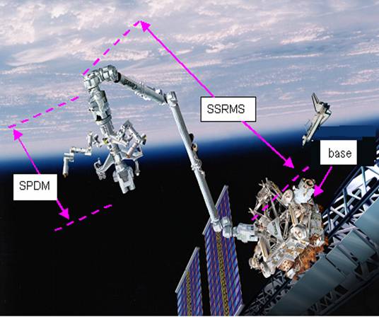
The Canadian Mobile Servicing System (MSS) is a 22 Degree-of-freedom robot system that is composed of a base, the SSRMS (Space Station Remote Manipulator System, also known as Canadarm2) and SPDM (Special Purpose Dextrous Manipulator System). Current motion planning for MSS is divided into two separate phases: posture planning and path planning. Posture planning is done by trial-and-error, which is highly human-involved and labor-intensive. This thesis treats the two separate phases above as one integrated problem, and develops automatic off-line motion planning methods for MSS to perform repair tasks in the International Space Station (ISS), while satisfying multiple task constraints, the most novel being that the worksite of the manipulators must be visible to various cameras mounted on different parts of the MSS.
We broke down the overall motion planning for the ISS repair task into a series of basic motion planning sub-problems. When solving these sub-problems, we modified some existing methods to take into account camera constraints in our application, and improved some methods to speed up the motion planning process. Through these automated methods, we are able to solve the motion planning for the MSS in most repair tasks in about thirty minutes, thereby leading to great savings in time.
The Mobile Servicing System (MSS):
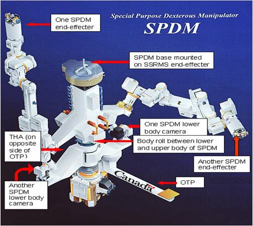
One of Canada’s contributions in the International Space Station (ISS) is the Mobile Servicing System (MSS). It is composed of three main components: (A) a base; (B) SSRMS (Space Station Remote Manipulator System, also known as Canadarm2), a 7 DOF manipulator; and (C) SPDM (Special Purpose Dexterous Manipulator), a dual arm system with each arm being a 7 DOF manipulator. The two arms are located at the upper body of SPDM. The lower body of SPDM is equipped with two cameras, and other components, such as OTP (ORU Temporary Platform, where ORU stands for Orbital Replacement Unit) and THA (tools holder). In addition, there are two cameras mounted on the boom of the SSRMS. We will subsequently see that the SSRMS boom camera and the lower body cameras are the ones that are supposed to monitor the repair task. There is an extra degree of freedom--a body roll between the upper and lower bodies of SPDM. The MSS therefore has 22 degrees of freedom.
The ISS repair task:
The ISS repair task is that the MSS travels to a position near a work site, a position where an Orbital Replacement Unit (ORU)--we can consider it as a mechanical part in ISS--has failed, remove the failed ORU, and install a new ORU in the same location using the SSRMS and SPDM. This task is composed of a series of sub-tasks, and each sub-task requires movement of SSRMS or one arm of SPDM. In all sub-tasks, the object being manipulated must be watched by at least one of four cameras---two SSRMS boom cameras and two SPDM lower body cameras. Some of the sub-tasks require that one of the two SPDM arms grasp special holding fixtures (H-fixture) on the ISS to stabilize the whole MSS.
My automatic off-line method:
My method divided the whole ISS task into a series of sub-tasks, and solved those sub-tasks in order, while satisfying all camera constraints. Finally, the method outputted a collision-free path, along which the MSS travelled and performed the whole ISS repair task. The whole task can be planned within about 30 minutes by my method.
I implemented this method in the Motion Planning Kernel (MPK), a software library developed at Robotics Lab, Simon Fraser University, Canada. A simulation that shows MSS travelling along the collision-free path obtained by my method is available. In this simulation, the four green cones represent the field of view of the four cameras. For each manipulation, the four cameras must look at the object being manipulated.
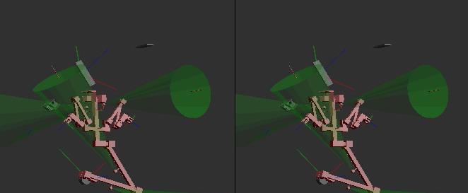
Click to download the video of the simulation based on planning result of my method.