Matlab/Simulink Real-time Control of a Mechatronic System using Freescale HCS12 MCU
Prepared by: Yaser M. Roshan, M. Moallem
School of Engineering Science, Simon Fraser University
In this project a platform for embedded target Freescale HCS12 using Matlab/Simulink toolboxes have been developed. The topics to be discussed in this page include implementing HCS12 Block-set in Matlab/Simulink and generating its C code to be run using CodeWarrior IDE. A mechatronic system consisting of a robotic arm and its interface with the above environment is developed during this project. The steps of this project can be summarized as bellow:
Index
Developing the Baseline Target
Implementing PWM Block for HCS12 MCU
Implementing Encoder Interface Block for HCS12 MCU
Implementing Encoder Interface
1DOF Robotic Arm Control Using HCS12
Developing the Host Target in Matlab requires two different steps [1]:
1-1) Developing the Baseline Target
Creating a baseline target includes several steps [1]. This steps are presented in this section, briefly. More description of these steps, can be found on the Mathworks website [2].
After creating the Baseline Target, the next step is creating the Block-set [1]. There are two common ways to create the Block-set. The first way is using Legacy Code Tool (LCT). Existing C (or C++) functions can be integrated into Simulink models using legacy Code Tool. This tool transforms existing functions into C MEX S-functions that can be included in Simulink models. This tool can also produce TLC files to inline the S-functions and use them in generated codes. Using the Legacy Code Tool has different steps. These steps are as follows:
The second way for creating Block-set is creating the appropriate files from scratch. In this way, the TLC file and S-function of each block should be generated separately. The C MEX S-function can be generated from the S-function and the TLC file will have the responsibility of modifying the generated codes. As in this page this method will be used, an overview of the S-Functions in Matlab have been presented in the next section.
1-2-1) Introduction to S-Functions
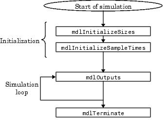
S-functions provide a powerful mechanism for extending the capabilities of the Simulink environment [3]. An S-function is a computer language description of a Simulink block. The S-function codes can be written an MATLAB, C, C++ or Fortran. In this projects the codes are written by C. Figure 1 demonstrates a block diagram of how the Simulink engine performs a simulation. Also Figure 2 demonstrates the codes which are necessary to build any S-function.
Figure 1. Simulation steps in Matlab/Simulink.
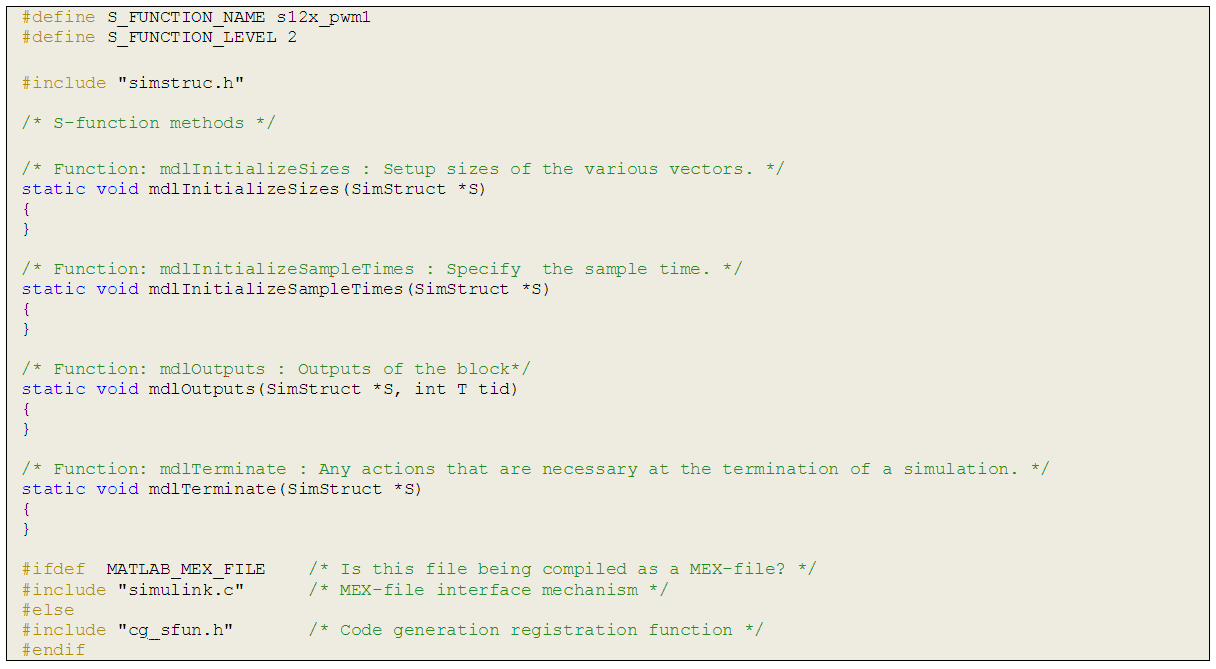
Figure 2. S-Function template.
The first two lines of the codes, introduces the S-function name and its level. The important concept about this template is, the four S-function call-back methods which are defined in this code (mdlInitializesizes, mdlInitializeSample Times, mdloutputs and mdlTerminate), are mandatory parts of any S-function codes. This functions define the operating conditions of the block. mdlInitializesizes is a call-back method which describes the number of inputs, outputs and parameters of the block. This function will initialized the parameters as well. mdlInitializeSample defines the sample time for the block. The sampling time can be either inherent or can be defined by the user. mdloutputs is an important call-back of the S-functions, which defines the outputs of the block. Finally mdlTerminate is called whenever the simulation ends.
2) Implementing PWM Block for HCS12 MCU
One of the major features of Matlab is its capability to generate codes from a Simulink model, which can be used on the microcontrollers. Implementing a block in Matlab/Simulink for using in microcontrollers, requires both knowledge of building Simulink blocks using S-Functions and also ability to write codes in Target Language Compiler (TLC) format. Figure 3 demonstrates how the Target Language Compiler fits in with the Real-Time Workshop code generation process [4].
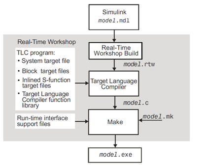
Figure 3. Code generation process.
The TLC is designed for one purpose, which is converting the model description file model.rtw into target-specific code. In the code generation process, the Real-Time Workshop, builds the model.rtw file from the Simulink model model.mdl. The model.rtw file can be modified later using TLC files. For the next step, there are two different types of TLC files; Modelwide TLC and Block TLC, which in the Figure 3 these files are referred as System target file and Block target file, respectively.
The modelwide TLC has the responsibility of building the general structure of code generation for a model. Each target environment of Real-Time Workshop has a set of modelwide TLC files related to it. These files will use the Block TLCs and other related functions to generate codes for the model.
The block TLC files are related to the generation of codes for a specific block. For example, all of the Simulink blocks of Matlab have the appropriate TLC file which is written by Mathworks. Each used defined blocks, should have their own TLC file. In the following parts of this page, the TLC file for PWM block is discussed.
Besides the TLC files, to create a PWM block, an S-Function should be created. The S-Function structure is described in the following parts of this page. Using TLC files and S-Function, Matlab will create the source files model.c and also make files model.mk. These files will be used during the make process to build the executable file model.exe.
In this part a S-Function is built using C. In the first lines of the S-Function, its name is defined as s12x\_pwm1. Also the level of the S-function is defined as level 2. In the mdlInitializeSizes, one input and one parameter is defined for the block. As this block has no output, there is no need for definitions of the output. Here the input is supposed to be the duty cycle (which will be the output of the controller block) and also the parameter is the period of the PWM signal, which is fixed and can be tuned by the user. At the mdlInitializeSampleTimes, the sample time of the block is set to INHERITED\_SAMPLE\_TIME. As there is no output for this block, therefore, the mdlOutput function doesn't have anything. Also, as the simulation will be run on the micro controller, there is no need for codes in mdlTerminate call-back method either.
When the codes for the S-Function finished, the command mex s12x\_pwm1 will create the MEX function. As the MATLAB is run in the 32 bit Windows, the final MEX function will be of type .mex32.
In the next step, the TLC file should be written. This file will help to modify the codes which will be generated during the Build process. In the first part of the file, driver\_utils.tlc is being included. In this file a record is added to the model.rtw file, which contains the definitions of the PWM registers in the HCS12 microcontroller. The pwmRegs() function which is defined in driver\_utils.tlc is as follows:
%function pwmRegs()
%createrecord regs {...
PWMPRCLK "PWMPRCLK"...
PWMSCLB "PWMSCLB"...
PWMCLK "PWMCLK"...
PWMPOL "PWMPOL"...
PWMCAE "PWMCAE"...
PWMCTL "PWMCTL"...
PWMPER2 "PWMPER2"...
PWMDTY2 "PWMDTY2"...
PWMCNT2 "PWMCNT2"...
PWME "PWME"...
}
%return regs
%endfunction
The above function, will create a record in the model.rtw file which has the fields with the name of the PWM registers in it.
In the next step, the header files for the board are being included to the codes. The next step will be initialization of the block. In this part, a function, Start, is defined which initializes the PWM registers. In this function, first the pwmRegs() function, is called and the result is saved in a variable ,reg.
%assign regs=PWMregs()
The next part reads the period as a parameter of the PWM block and saves it in a variable, pwmPER.
%assign pwmPER=CAST("Unsigned",SFcnParamSettings.PWMPERbyteValue)
The final part of the Start function is assigning the PWM registers. The following lines are two samples of how this is done.
%<regs.PWMPRCLK>=0x30;
%<regs.PWMPER2>=%<pwmPER>;
The next function in the TLC file is the Outputs function, which is responsible for code generation for mdlOutputs function. In this function, again the pwmRegs() function is called and the variable pwmPER is read from the block parameters. Also the following code reads the block input and saves it in a variable, u.
%assign u=LibBlockInputSignal(0,"","",0);
The final codes of the function Outputs, are for assigning the input signal of the block as the duty cycle for the PWM. These codes are as follows.
if (%<u> < %<pwmPER>) {
%<regs.PWMDTY2>=%<u>;
} else {
%<regs.PWMDTY2>=%<pwmPER>;
}
The final function which is defined in the TLC function is the Terminate function. In this function after calling the pwmRegs(), the PWM enable register, PWME, is assigned to zero, to disable the PWM of the micro-controller.
%<regs.PWME>=0x00;
Figure 4 demonstrates a simple block diagram of Simulink file for using the PWM block. Using these blocks and by changing the input constant number, user can make any PWM signal with the micro controller.
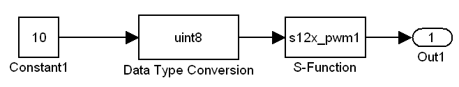
Figure 4. Simulink diagram of PWM block usage.
To build the model and generate appropriate codes, some parameters of the Simulink should be set. To apply these settings, the user should open the ``Configuration Parameters" window of the model, from the ``Simulation" menu. In "Solver" tab, the Type should be set to "Fixed-step" while the Solver is set to "discrete (no continuous states)".
In "Real-Time Workshop" tab, the System target file should be "s12x.tlc". Also in "s12x Target Options" pane, the Board Frequency should be "4000000" and the Actions should be "Run". After applying these setting one can Build the model using Ctrl+B shortcut. When the Build process starts, the process is described in the Matlab Command Window. The descriptions contain the generation of all the related files. When the code generation process is finished, the Real-Time Workshop Report window will show the codes which are generated. Then, for the target action, run, the .mcp project will be ran on CodeWarrior software. Figure 5 demosntrates the files which are built in the project. If the MCU board (DEMO9S12XDT512), is connected to the USB port, the project will be loaded to the micro-controller.
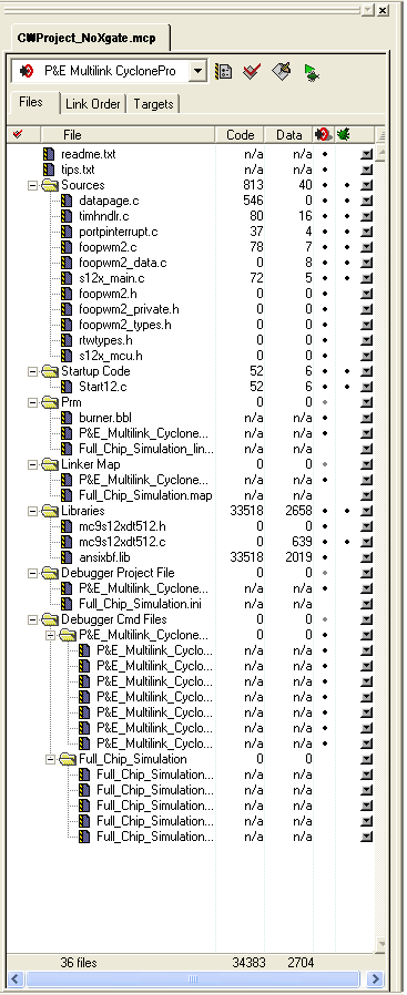
Figure 5. Files in the CodeWarrior project.
3) Implementing Encoder Interface Block for HCS12 MCU
In order to monitor the position of the DC motor, one can use different kinds of sensors such as encoders, potentiometers, infrared sensors, etc. In this work, our purpose is working with incremental encoder to sense the position of the motor. In order to use the encoder, one should be able to work with timers and counters of the microcontroller. Therefore, in this section the incremental encoders and the timer registers of the micro controller are described, briefly. Then the codes which are written to generate appropriate C codes for the encoder interface, are covered.
Figure 6 demonstrates the block diagram of the timer module of the microcontroller [5]. As it is illustrated in Figure 6, the timer module shares the use of Port T pins PT0-PT7. The signal pins IOC0-IOC7 correspond to PT0-PT7. Also Figure 7, illustrates the internal view of the sub-modules of the 16-bit 8 channel timer.
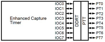
Figure 6. Timer module block.
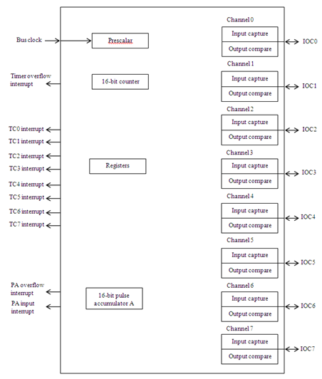
Figure 7. Timer internal block diagram.
Timer has different registers which should be set, separately. In this section, these registers are introduced briefly.
3-3) Implementing Encoder Interface
HCS12 has 2 important registers which are 16-bit Pulse Accumulators. These accumulators can also be divided to 4 8-bit accumulators. After enabling each of these registers, and attaching a pulse to the proper pins of port T, these registers will count the number of falling or rising edges in the pulse. One good idea to use these accumulators in order to find the position (count the encoder pulses appropriately), is modifying the encoder outputs to provide proper signals. These proper signals are in a way that, whenever the motor is rotating clockwise, one of them will be having the pulses, and whenever the rotation direction is counter-clockwise, the other one will have the pulse. Therefore, just by counting the pulses, each accumulator can have the number of clockwise or counter-clockwise pulses at each time. Subtracting these two from together, will give us the position of the motor.
3-3-1) Quadrature Encoder Interface
LS7184 is a quadrature encoder interface chips. This IC can have two encoder channels as the input and can provide an output which can specify the direction of rotation. The schematics of this IC is shown in Figure 8.
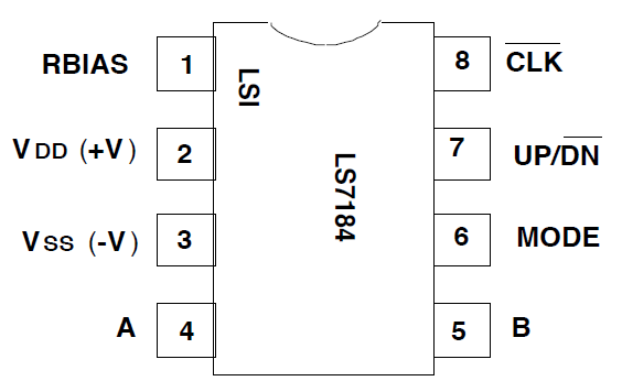
Figure 8. Quadrature encoder interface.
The output channels of encoder (A and B), are connected to the input pins of the IC (4 and 5). One of the outputs of the IC, UP/DN, will define whether the rotation is clockwise or counter-clockwise, by being 1 or 0. Figure 9, illustrates the relation between inputs and outputs of the IC.
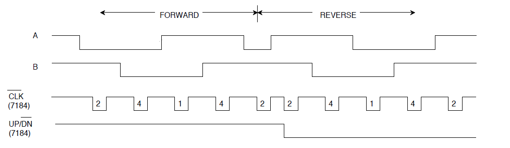
Figure 9. LS7184 outputs.
The next part of the modification of encoder outputs is using the simple circuit which is shown in Figure 10. The outputs of this circuit will be two pulses. The first pulse will have the same pulse as Channel A of encoder, as long as the motor is rotating in clockwise direction. Otherwise, it will have zero. The second pulse will be the same as Channel B of encoder, as long as the motor is rotating in counter-clockwise direction. It will be zero, if the direction of rotation is clockwise.
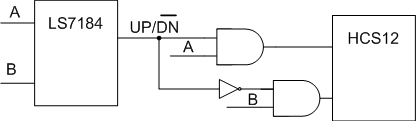
Figure 10. Interface circuit.
In the microcontroller, HCS12, the codes for the Encoder block, should be able to enable the pulse accumulators and set the appropriate registers. The c-file has nothing new, than the previous c-file written for the encoder. However, the tlc-file, will have some changes. In the BlockInstanceSetup function, there will be a new int16 variable, named PS12XencoderCtr. This variable is defined as follows:
extern int16_T S12XencoderCtr
In the Start function, the codes for enabling the encoder is written. Different registers should be set during this step. For pulse accumulator A, PACTL is the enable register. Also this register will define the rising (or falling) edge detection for this pulse accumulator. In this work, the accumulator is set on rising edge. PBCTL, is the control register of pulse accumulator B. This register will enable the pulse accumulator, but it cannot specify the edge. Therefore, using TCTL4 register, one can define rising edge for the proper pin of port T. As both inputs should be connected to port T (PT0 and PT7), this pins should be defined as inputs using DDRT register. The last part is initializing the accumulators using PACN32 and PACN10 registers. The codes for this part are as follows:
DDRT &= 0x81;
PACTL = 0x50;
PBCTL = 0x40;
TCTL4 = 0x01;
PACN32 = 0;
PACN10 = 0;
In the Terminate function, the same codes which are used for initialization are used in order to set the accumulators to zero. The last part of the TLC-function is the Outputs function. For this part, we need to define the accumulators registers in the driver\_utils.tlc file. Doing this will be done as the following lines:
%function encRegs()
%createrecord regs {...
PACN32 "PACN32"...
PACN10 "PACN10"...
}
%return regs
%endfunction
After defining the accumulator registers, the output of the block, should be defined in the Outputs function. This part is done as the following:
%assign y=LibBlockInputSignal(0,"","",0);
%assign regs=encRegs();
%<y>=(%<regs.PACN32>-%<regs.PACN10>)+10000;
where 10000 is the bias value for the counter, which is used in this work, in order to prevent the value of counters to be negative. Therefore, the output of the block is defined as the number of pulses which is passed, assuming +1 for clockwise pulses and -1 for counter-clockwise, plus the bias value 10000. Hence, in the Simulink a subtraction and a gain is needed, to change the output of the block to degree.
Figure 11, illustrates the usage of the encoder block. In this sample work, the output value is passed through an Abs block, because the purpose of the test program, was to turn on an LED whenever, the motor angle is out of an specific range (e.g. -30 to +30 degrees). Also the usage of the Gain block is for changing the number of the pulses passed to degrees. Figure 12, demonstrates the circuit which is implemented for encoder interface.
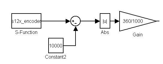
Figure 11. Encoder block Simulink.
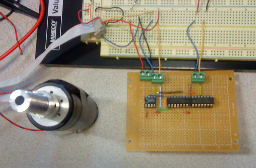
Figure 12. Encoder Interface circuit.
4) 1DOF Robotic Arm Control Using HCS12
The next step of this project is building an integrated sample system which consists of a 1 DOF robotic arm control and control it using MATLAB/Simulink environment and HCS12 micro controller. The setup for this project is made as it is shown in Figure 13. This setup is consists of two different actuators, a DC motor and a Magnet, and also two different position sensors, an Encoder and a Potentiometer. In this step of the project, just the DC motor and the Encoder are used in order to control the position of the motor and make it move back and forth between two different points.
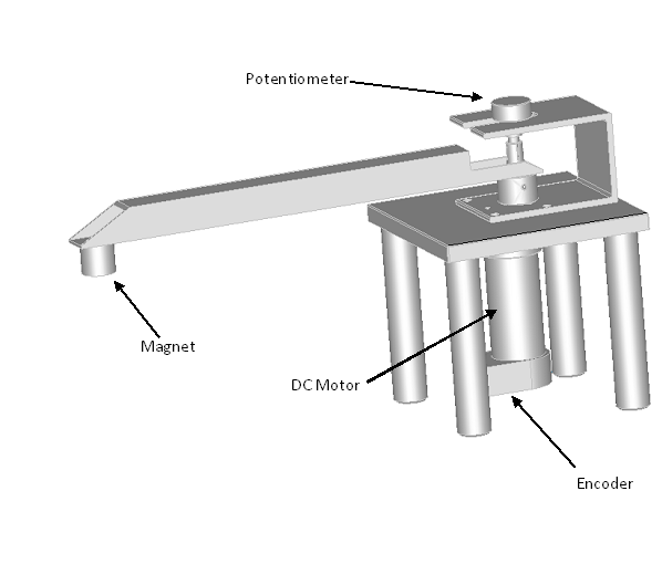
Figure 13. 1DOF robotic arm setup.
All of the individual parts of the projects have been described completely in the previous sections. In this section the whole setup and the Matlab/Simulink file which are used, are described. Figure 14 demonstrates the control part of the system which is designed in the Matlab/Simulink environment.
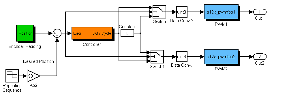
Figure 14. System control unit in Matlab/Simulink environment.
The Encoder Block has the same structure as in the Figure 11. The output of the encoder block which is the actual position of the motor, is then compared with a repeating sequence which simulates two different position (in this example 90 degrees), as the desired position. The error is then fed to a controller which here is a simple P controller. Based on the value of the error a duty cycle is created and will be applied to the PWM blocks. The switch blocks are working based on the sign of the error. If the error is greater than zero, Out1 will have the PWM signal and a zero will be sent to the PWM2 block as it's duty cycle. Otherwise, if the error is lower than zero, the output of the controller will be conducted the PWM2 block and PWM1 will have zero as its duty cycle. In the final circuit, Out1 and Out2 will be connected to IN1 and IN2 ports of the TA7267BP chips.
In order to generate C codes for this Simulink model and also download the C codes on the HCS12 micro-controller, one should add the appropriate TLC and MEX files which have been created and described in the previous sections, to the proper folders (Blocks Folder of the Host Target root).
Figure 15 demonstrates the setup and the circuits which are created for this project. In the left part of the figure the circuits for DC motor drive and also the encoder reading circuit is demonstrated. The board in the right side of the figure, is the HCS12 evaluation board. In the middle part of the figure the 1DOF robotic arm can be seen. The motor is located under the arm; therefore, it's not visible in this Figure. The whole circuit diagram is also shown in Figure 16.
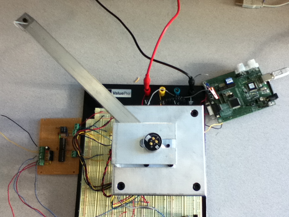
Figure 15. Robotic arm setup with the electrical parts.
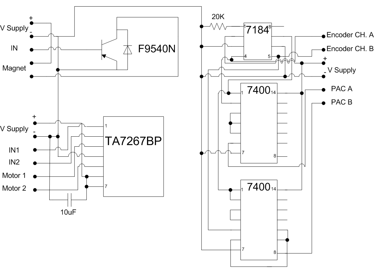
Figure 16. Circuit diagram of the electrical parts.
After building the Simulink model and downloading it on the target (HCS12), and also supplying the circuits with appropriate voltage supplies, the setup will work properly. The arm will go back and forth between two desired points.
As future steps of this project, the magnet drive circuit and block diagrams can be implemented, and also a state-flow control algorithm can be used to determine the times when the magnet should be turned ON or OFF.
[1] "S12x Demo Kit: For use with Freescale CodeWarrior Development tools", The Mathworks, November 2009.
[3] "Developing S-Function", The Mathworks, Revision: September 2010.
[4] "Real-Time Workshop 7: User's Guide", The Mathworks, Revision: September 2010.
[5] H. W. Huang, "The HCS12/9S12: An Introduction to Software and Hardware Interfacing", Thomson Delmar Learning, 2005.