

|
|
|
|
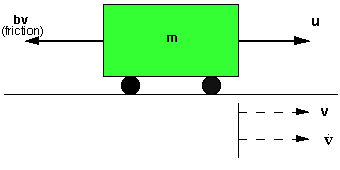
The model of the cruise control system is relatively simple. If the inertia of the wheels is neglected, and it is assumed that friction (which is proportional to the car's speed) is what is opposing the motion of the car, then the problem is reduced to the simple mass and damper system shown below.
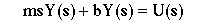
Using Newton's law, modeling equations for this system becomes:
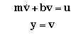 (1)
(1)where u is the force from the engine. For this example, let's assume that
The next step in modeling this system is to come up with some design criteria. When the engine gives a 500 Newton force, the car will reach a maximum velocity of 10 m/s (22 mph). An automobile should be able to accelerate up to that speed in less than 5 seconds. Since this is only a cruise control system, a 10% overshoot on the velocity will not do much damage. A 2% steady-state error is also acceptable for the same reason.
Keeping the above in mind, we have proposed the following design criteria for this problem:
Rise time < 5 sec
Overshoot < 10%
Steady state error < 2%
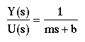
To find the transfer function of the above system, we need to take the Laplace transform of the modeling equations (1). When finding the transfer function, zero initial conditions must be assumed. Laplace transforms of the two equations are shown below.
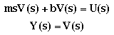
Since our output is the velocity, let's substitute V(s) in terms of Y(s)
The transfer function of the system becomes
To solve this problem using Matlab, copy the following commands into an new m-file:
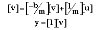
We can rewrite the first-order modeling equation (1) as the state-space model.
step (u*num,den)
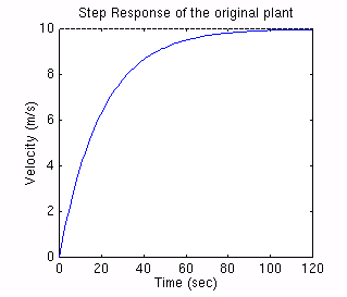
You should get the following plot:
To use the m-file written for the state-space (the m-file with A, B, C, D matrices), add the following command at the end of the m-file and run it in the Matlab command window:
step (A,u*B,C,D)
You should get the same plot as the one shown above.
From the plot, we see that the vehicle takes more than 100 seconds to reach the steady-state speed of 10 m/s. This does not satisfy our rise time criterion of less than 5 seconds.
To solve this problem, a unity feedback controller will be added to improve the system performance. The figure shown below is the block diagram of a typical unity feedback system.
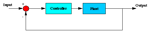
The transfer function in the plant is the transfer function derived above {Y(s)/U(s)=1/ms+b}. The controller will to be designed to satisfy all design criteria. Four different methods to design the controller are listed at the bottom of this page. You may choose on PID, Root-locus, Frequency response, or State-space.


